Sign Language Glove
The Sign Buddy system is composed of a sensing glove and an Android application. The app wirelessly sends commands over Bluetooth Low Energy (BLE) which tell the glove to start sampling its sensors. The glove responds to the app with the sensor readings, and the app uses the readings to perform gesture classification using a supervised machine learning model.
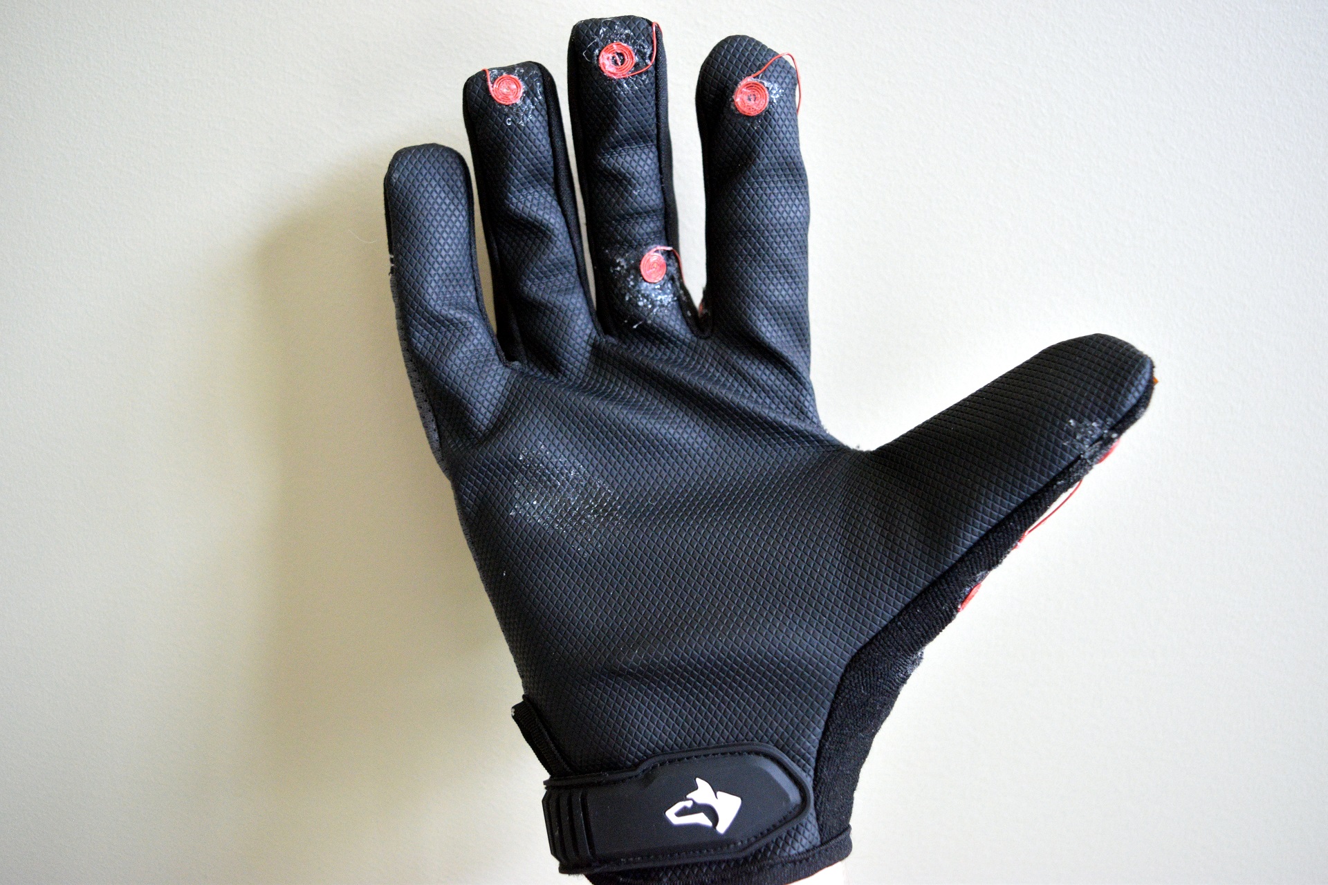
The Sign Buddy glove houses 12 capacitive touch sensors, 5 flex sensors along the joints of the fingers, and the Sign Buddy printed circuit board (PCB).
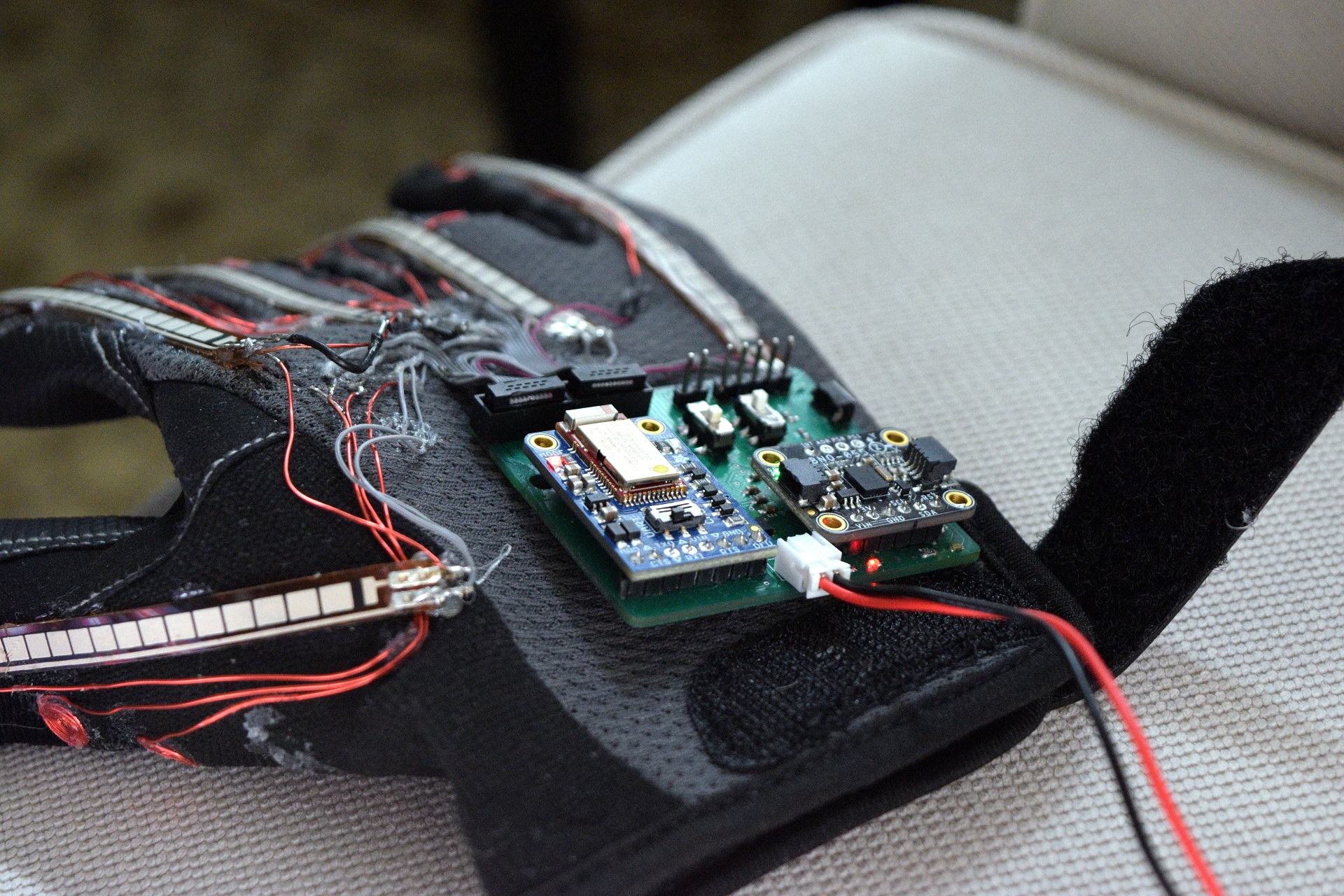
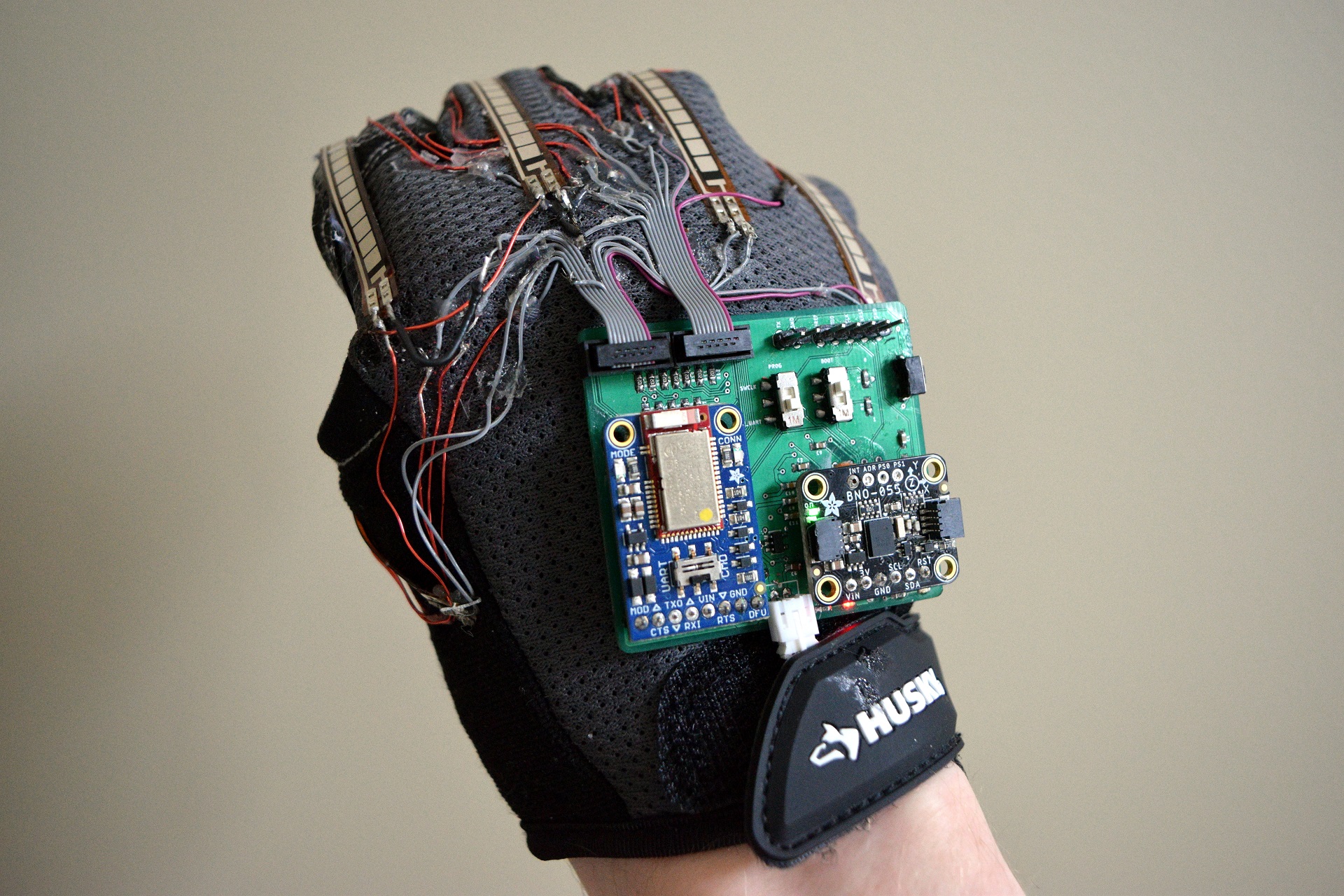
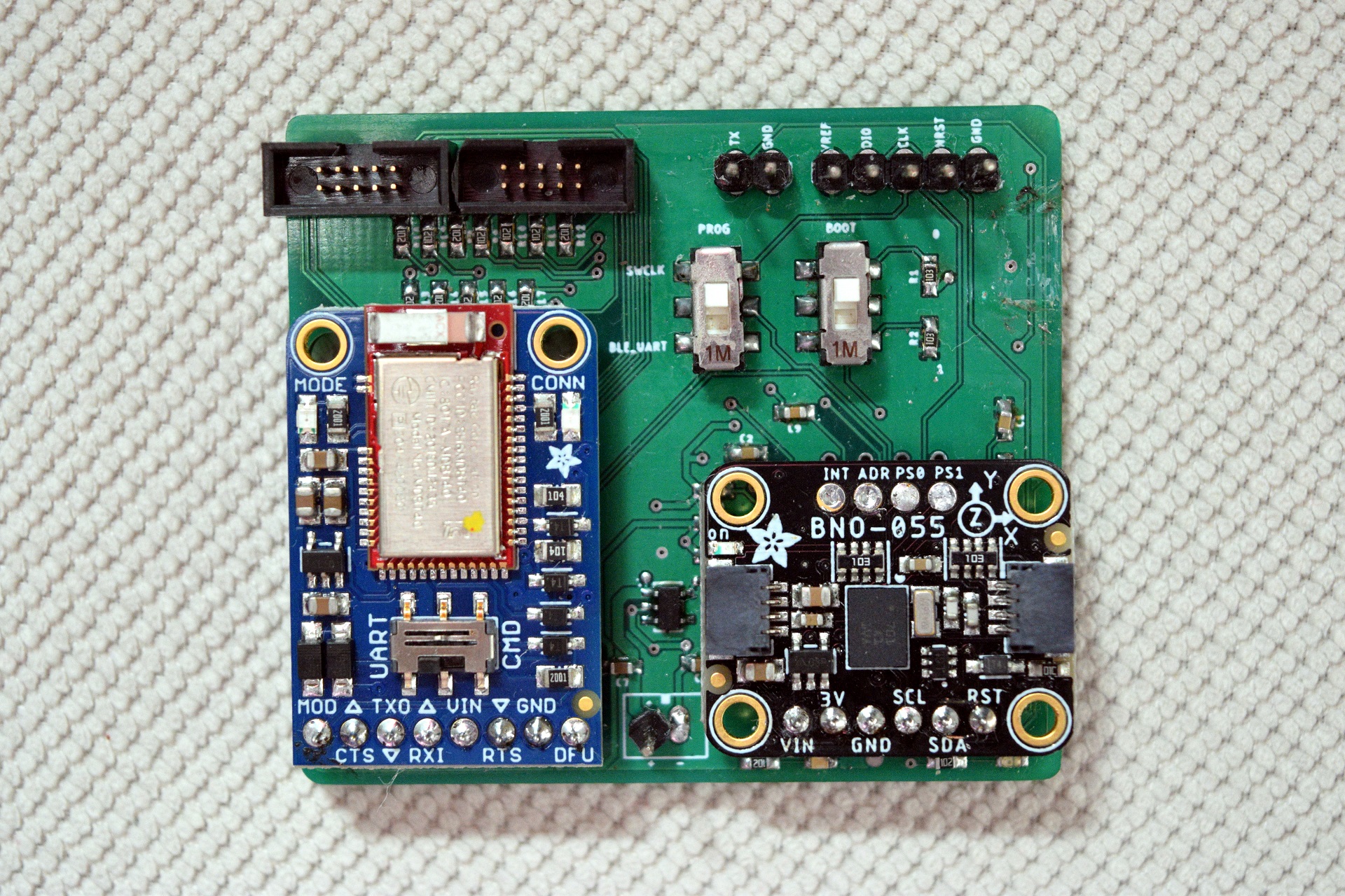
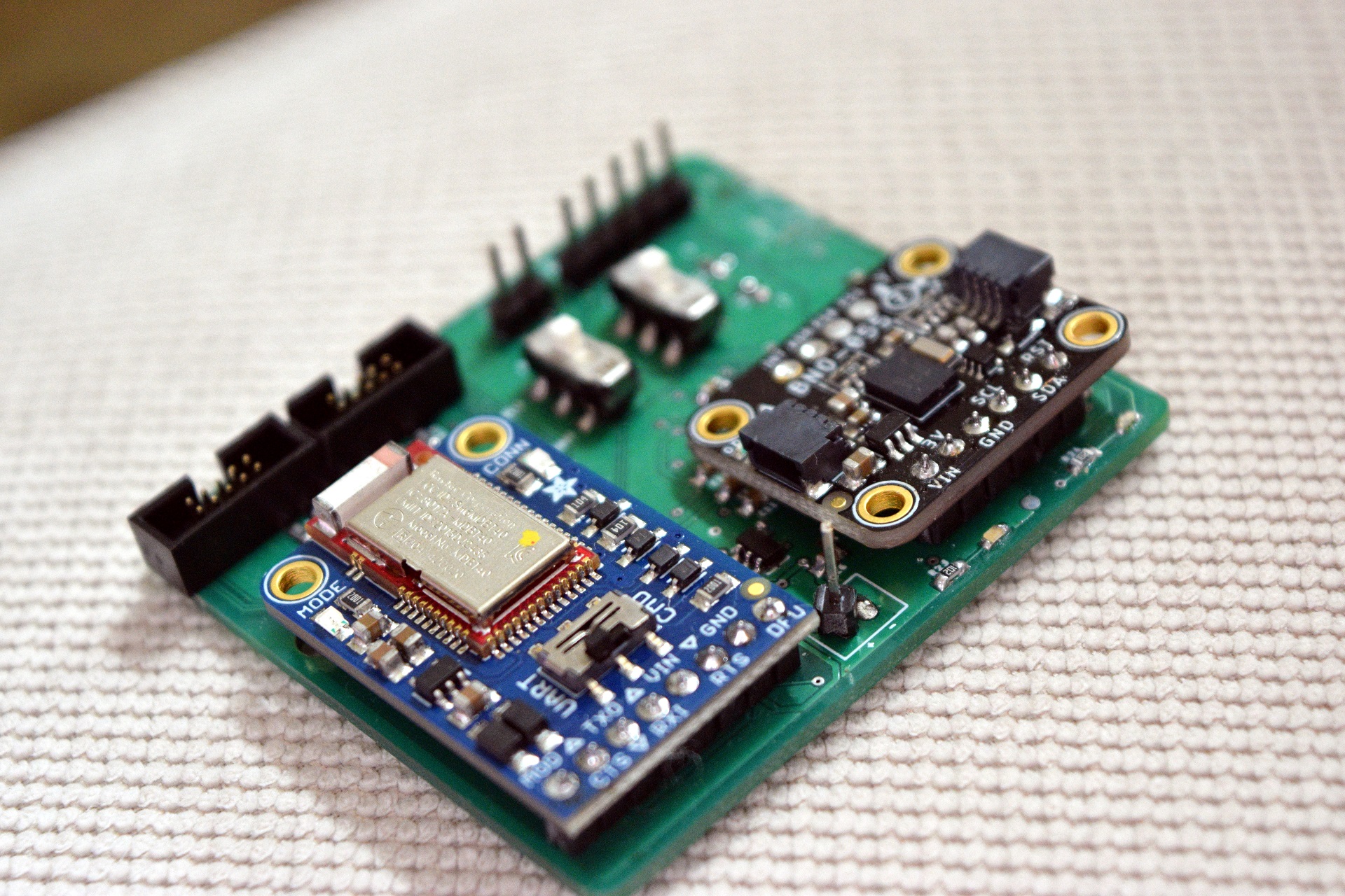
The Sign Buddy PCB houses an STM32L053R8 microcontroller (MCU) which is responsible for sampling the glove’s sensors. The MCU was chosen for its ultra-low-power consumption due to the usage of an Arm Cortex-M0+ which is Arm’s most energy-efficient processor.
In addition to the MCU, the PCB houses the Adafruit Bluefruit LE UART Friend. The BLE Friend permits the MCU to wirelessly talk to an Android device using the MCU’s UART peripheral. The BLE UART module was chosen to reduce the development time needed for wireless communication.
Finally, the PCB houses the Adafruit BNO055 Absolute Orientation Sensor. The BNO055 includes a 9-axis inertial measurement unit (IMU) with an accelerometer, gyroscope, and magnetometer. The IMU performs on-board sensor fusion which makes it simpler to determine the glove’s orientation.
The Sign Buddy firmware is organized into modules corresponding to the sensors on the glove. As depicted below, a hierarchical architecture was implemented utilizing an application layer, board support package (BSP), real-time operating system (RTOS), and hardware abstraction layer (HAL). FreeRTOS was utilized to support multitasking among the application layer modules.
There are 5 tasks that run in the system with priorities shown below:
| Task Name | Priority |
|---|---|
| TSC | Highest |
| Flex | Highest |
| IMU | Highest |
| Sensors | Medium |
| Comms | Lowest |
The touch sensing (TSC), flex, and IMU tasks run at the highest priority and are responsible for collecting data from their respective sensors.
On start-up, the collection tasks are blocked on a task notification, which is a lightweight synchronization tool in FreeRTOS, are are unblocked by the sensors task as necessary.
The TSC task is responsible for collecting data from the 12 touch sensors using STM32’s TSC HAL. 3 channels are used with 4 touch sensors allocated to each channel.
The flex task is responsible for collecting data from the 5 flex sensors using the STM32’s analog-to-digital converter (ADC) with direct memory access (DMA).
The flex sensors act as variable resistors in the range of 10-20K based on the flex. To get a measure of the angle of rotation, voltage dividers were used by placing each sensor in parallel with a 10K resistor. The voltages were measured using the ADC and readings were linearly calibrated in the range of 0 to 90 degrees.
The ADC was disabled when the system was idle to minimize power consumption.
The IMU task is responsible for collecting data from the BNO055 using I2C. Quaternion values were read from the IMU.
Additionally, the IMU task checks if the IMU module is calibrated by requesting calibration status from the BNO055. If the IMU is not calibrated, a status LED is enabled to indicate to the user that the calibration procedure needs to be performed before using the device.
The sensors task triggers the collection tasks to collect data and passes the data to the communications task.
A 20Hz software timer was used to unblock the collection tasks’ task notifications. The sensors task blocks on an event group until all sensor data is collected, then passes the data to the communications module and blocks on a task notification until the next timer tick.
After the sensors task collects the max number of samples for a gesture (1 or 40 depending on whether the letter is a static or time-dependent gesture), the software timer is disabled and collection stops until a command is received in the communications task to start sampling.
The comms task receives commands and wirelessly transmits sensor data to the Android application over Bluetooth.
The task runs in a polling fashion which monitors a flag set by the sensors task to check if new sensor data is ready to be transmitted. If new data is ready, the data is serialized and ingested into a FIFO buffer for transmission. Then, the task processes any received commands, and finally transmits any data in the transmission buffer.
The comms task is capable of processing 3 commands as described below:
| Command | Code | Description |
|---|---|---|
| CMD_SAMPLE_STATIC | 0x01 | Trigger sensors task to sample once |
| CMD_SAMPLE_DYNAMIC | 0x02 | Trigger sensors task to sample 40 times at 20Hz |
| CMD_RESET_IMU | 0x03 | Software reset the IMU |
Feel free to check out the source code on GitHub.
